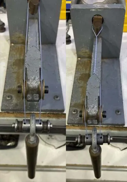
For engineers in the transformer industry who are used to working with solid conductor winding wires, the larger diameters and wider tolerances on Litz wires may come as a bit of a shock. With Litz wires, overall diameters are larger and copper density is lower than on a solid conductor equivalent due to air gaps between the strands and the enamel layer around each strand.
To give a few examples:
Table 1: Single Build Bare Magnet Wire and Bare Litz
| 12 AWG Single Build (Grade 1) Magnet Wire | 12 AWG 400/38 Single Build Litz PN: RL-400-38S80-01 | |
| Min OD | .0814” (2,068mm) | .1038” (2,068mm)* |
| Nom OD | .0827” (2,101mm) | .1112” (2,101mm)* |
| Max OD | .0840” (2,134mm) | .1192” (2,134mm)* |
*PLEASE NOTE: LITZ CONDUCTOR DIAMETERS CAN VARY BY SUPPLIER.
Table 2: Triple-Insulated Solid Tinned Copper Wire and Triple-Insulated Litz Wire
| 18 AWG Solid TPC TIW PN: T18A01TXXX-1.5 | 18 AWG 105/38 LITZ TIW PN: TXXL105/38TXXX-1.5(MW80) | |
| Min OD | .0483” (1,227mm) | .058” (1,473mm)* |
| Nom OD | .0493” (1,252mm) | .062” (1,575mm)* |
| Max OD | .0508” (1,290mm) | .066” (1,676mm)* |
*PLEASE NOTE: LITZ DIAMETERS CAN VARY BY SUPPLIER.
As you can see, overall diameters on Litz wires are significantly larger than on solid conductor equivalents. Two things contribute to the larger diameters: the packing density of stranded conductors and the added insulation layer over each individual strand. Packing density peaks out at approximately 80% for high end-count bunch-stranded conductors. The rest of that volume is filled by air gaps between the strands. With Litz wires, the enamel layer over each individual strand also adds to the diameter of the overall conductor.
Tolerances on the overall diameter are also wider for Litz wires than they are for a solid conductor equivalent. To explain why, a bit of math will be required. Consider the diameter approximation formula for a bunch stranded conductor:
Equation 1: Bunch Stranded Conductor Overall Diameter Approximation
D = P*d* √(n)
P = Packing factor (1.155 for bunch-stranded conductors)
D = Overall diameter
d = Diameter of individual strands
n = Total number of strands
With bunch-stranded Litz wires, minimum and maximum magnet wire diameters can be plugged into the equation above in order to calculate minimum and maximum overall wire diameters. Let’s take a look at that in the case of a simple 20 AWG 65/38 Litz conductor.
Table 3: Bunch-stranded Single Build 65/38 Bare Litz Wire Dimensions
| Minimum | Nominal | Maximum | |
| d | .0042” (0,107mm) | .0045” (0,114mm) | .0047” (0,119mm) |
| Δd | -.0003” (-0,0076mm) | – | +.0002” (+0,0051mm) |
| n | 65 | 65 | 65 |
| √n | 8.062 | 8.062 | 8.062 |
| D | .0391” (0,993mm) | .0419” (1,064mm) | .0438” (1,113mm) |
| ΔD | -.0028” (-0,0711mm) | – | +.0019” (+0,0483mm) |
Even in this case of a very simple bare Litz wire construction produced in a single bunching operation, we effectively have an OD tolerance of +.002”/-.003”. That tolerance is already wider than what one would see on an insulated winding wire with a solid 20 AWG conductor. From here, diameter tolerances can only get wider if a serve or insulation layer is added to the product, due to variations in the thickness of the serve or insulation layers.
With more complicated Litz wire constructions, especially those produced in multiple operations with changes in lay directions, tolerances can be even wider. Any increase in the Packing factor (P), the number of strands (n), or the delta in magnet wire diameters between nominal and min or nominal and max (Δd) will result in a wider overall diameter tolerance. With larger, more complicated Litz wire constructions, Δd will remain constant for a specified magnet wire size and build, but P and n may both be larger in the case of a more complicated Litz construction. The packing factor, P, can range from 1.155 for some unidirectional conductors to 1.54 for some very complex constructions with multiple changes in lay directions. Diameter tolerances are also directly proportional to √n, so it’s important to be aware of the fact that an increase to the total number of strands will result in wider diameter tolerances.
Need a Litz wire product designed to fit your unique application? Would you like some help with figuring out what Litz wire(s) can give you the desired number of turns in your winding window? Want some help with the calculations shown in this article? Contact our knowledgeable sales and engineering teams to discuss your application at sales@rubadue.com or +1(970) 351-6100.
Please note: There are no repeatable and reproducible methods for measuring overall diameters on flexible stranded conductors. Diameter measurements may vary from the values tabulated here due to error in the measurement method.
You May Like

Insulated Winding Wire 101: Selecting an Insulated Winding Wire Part I: Temperature Ratings
When designing or selecting an insulated winding wire for use in a wound component, it is important to consider the following: What is the range of operating temperatures that the product will see in your

The Different Test Methods Used for Electric Strength and Breakdown Voltage Testing on Winding Wires
There are three different test methods used for Electric Strength testing and Breakdown Voltage testing on winding wires. This article will give a brief description of each test method and outline the sizes of winding