The Different Test Methods Used for Electric Strength and Breakdown Voltage Testing on Winding Wires
Back to BlogThere are three different test methods used for Electric Strength testing and Breakdown Voltage testing on winding wires. This article will give a brief description of each test method and outline the sizes of winding wires that each test method should be used for. First, however, it would be prudent to differentiate between Electric Strength testing and Breakdown Voltage Testing.
Electric Strength Tests: The wire being tested must withstand the application of the test voltage for a specified period of time. Electric Strength tests are pass/fail tests. Breakdown of the insulation material before the required amount of time passes constitutes a failure. The wire is not tested until failure.
Breakdown Voltage Tests: A test voltage is applied and steadily increased at a specified rate until breakdown occurs. The voltage at which breakdown of the insulation material occurs is recorded as the result. Typically done on a group of five samples.
With those explanations out of the way, we can take a look at the three different test methods used for Electric Strength testing and Breakdown Voltage testing. The test methods come from IEC 60851-5. The tests methods used are referred to as the Metal Cylinder Test Method, the Twisted Pair Test Method, and the U-bend Metal Shot Bath Test Method in this article.
Metal Cylinder Test Method (Overall diameters up to 0.1mm):
A straight piece of wire with the insulation removed on one end is wrapped once around a polished metal cylinder with a diameter of 25mm. A load specified in IEC 60851-1 is applied to the wire to keep it in contact with the metal cylinder. The test voltage is applied between the wire and the metal cylinder.
Refer to IEC 60851-5 Clause 4.3 for additional information on this test method.
Twisted Pair Test Method (Overall diameters greater than 0.1mm and up to 2.5mm):
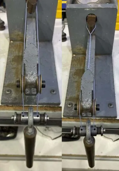
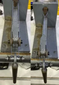
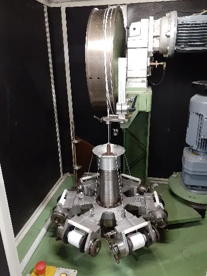
A straight piece of wire with the insulation removed from both ends is bent into a U shape and then twisted back on itself. A specified number of twists is applied to the wire over a length of approximately 125mm under a specified amount of tension. See Figure 1 for a visual on what the sample preparation process looks like.

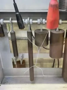
Once the wire has been twisted, the loop that is formed at the bottom of the “U” shaped bend is cut and the two cut ends are separated, resulting in a twisted pair specimen with two isolated conductors. Once the twisted pair sample has been produced, the test can begin. The specified test voltage is applied between the two legs of the twisted pair. See Figure 2 for a visual.

The test voltages specified for this test method are typically double the test voltages specified for the other two methods discussed in this article, since each leg of the twisted pair sample is insulated.
Refer to IEC 60851-5 Clause 4.4.1 for additional information on this test method.
U-Bend Metal Shot Bath Test Method (Overall diameters greater than 2.5mm):
A straight piece of wire is bent into a “U” shape with a specified bend radius. The “U” shaped sample is placed vertically in a plastic bucket partially filled with metal shot, typically made of steel, nickel, or nickel plated iron. Once the sample has been placed in the bucket, additional metal shot is slowly poured into the bucket to cover the “U” shaped sample to a depth of 90mm from the bottom of the “U”. The metal shot acts like the beads in a spark tester and completely surrounds the sample being tested. The test voltage is applied between the wire and the metal shot in the bucket.
Refer to IEC 60851-5 Clause 4.5.1 for additional information on this test method.
For higher voltage and specialty applications, Rubadue can work with customers to establish a custom electrical testing program using the twisted pair and U-bend test methods. Contact your account manager or customer service representative for more information.
Questions about the contents of this article or Rubadue’s product offerings? Contact our knowledgeable sales and engineering teams to discuss your application at sales@rubadue.com or +1(970) 351-6100.
You May Like

Insulated Winding Wire 101: Selecting an Insulated Winding Wire Part I: Temperature Ratings
When designing or selecting an insulated winding wire for use in a wound component, it is important to consider the following: What is the range of operating temperatures that the product will see in your

Litz Wire 101: When is a textile serve appropriate for your application?
Textile serves, when applied to Litz wires, act as an optional layer of added mechanical protection for the overall conductor. Serves are particularly effective at protecting the enamel layer on the individual strands of the